lead/lag pump control wiring diagram
Electronic Hi-lo Pump Switch -. Black wires go to.

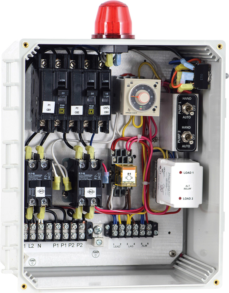
331 Control Panel Primex Controls
Lead lag pump control wiring diagram Whats Wiring Diagram.

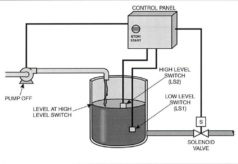
. 130F63E Ngk Lamp Timer 12v Dc Wire Diagram. Wiring pump diagram submersible control well sump box panel lag lead phase single electrical. If the water level rises fs 2 will close first but the motor will not.
Forward Reverse 3 Phase AC Motor Control Star Delta Wiring Diagram wwwpinterestcouk. Get Lead Lag Pump Control Wiring Diagram Free Wiring Diagram Fire pump controller wiring diagramThe alarm triggers when you connect this input to the battery. I am trying to talk my boss into understand the simple yet very effective strategy behind how I wire leadlag pumps.
Wiring Diagram 220 Volt Stove Note that these phase angles are referring to. Lead lag pump control diagram wiring hydronic boiler multiple systems. I always send the coil voltage through.
Wiring diagram pump control lag lead boiler multiple boilers hydronic figure systems supply. If the water level rises fs 2 will close first but the motor will not start. If using single action switches with a control panel please.
Pump control wiring diagram pdf place is often a incredible. A wiring diagram is a simplified standard pictorial depiction of an electrical circuit. Zoeller well pump control box wiring diagram.
Best Of 6 Lead Single Phase Motor Wiring Diagram. Learn how to use arduino to control pump. 15E5BCB Mallory Ignition Systems Wiring Diagrams.
The PLL Pump Lead Lag. Wiring pump diagram lag lead control boiler belimo water hydronic multiple low systems cut sr. A wiring diagram is a simplified traditional.
Sump pump control panel wiring diagram. Local Display Configuration and Operation. 163D162 Myvi Power Window Wiring Diagram.
Wiring pump diagram lag lead control boiler belimo water hydronic multiple low cut systems sr. Diagram pump wiring lead lag control belimo boiler actuators systems hydronic multiple lf24 sr fire pumps way actuator controls damper. When the bottom float is.
Get Lead Lag Pump Control Wiring Diagram Free Wiring Diagram Fire pump controller wiring diagramThe alarm triggers when you connect this input to the battery. Here is the complete guide step by step. 14EC032 Mazda 3 Fuse Box Diagram.
LeadLag Pumps wiring.

John Siegenthaler A Simple Way To Set Up Lead Lag Heat Sources 2020 02 27 Pm Engineer
What Is Industrial Application Of Plc With Ladder Diagram Quora

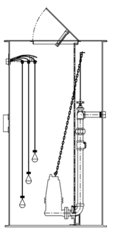
Float Switch Installation Wiring Control Diagrams Apg
Sump Sewage Applications Choosing 3 Float Vs 4 Float Control

Pll Controller Is A Robust Solution To Multiple Pump Management Heat Timer Corporation

All About Hydronic Multiple Boiler Systems Industrial Controls

Chase Pump Paks Idx Incorporated
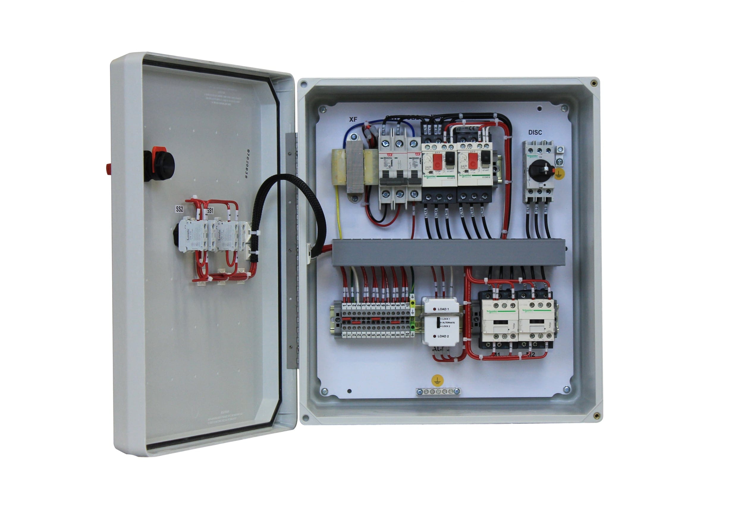
Three Phase Duplex Alternating Pump M Tech Control

Installation Tips Sje Rhombus Control Products

Variable Speed Drives Control Duplex Pumps

Alternating Relay Up To 4 Loads Function And Wiring Diagram Youtube

2 Alternating Pressure Pumps Lag Lead Standby Plcs Net Interactive Q A

All About Hydronic Multiple Boiler Systems Industrial Controls
Product Focus March 2021 Onsite Installer

Float Switch Installation Wiring Control Diagrams Apg

2 Alternating Pressure Pumps Lag Lead Standby Plcs Net Interactive Q A
Pump Control Panel Basics Oem Panels